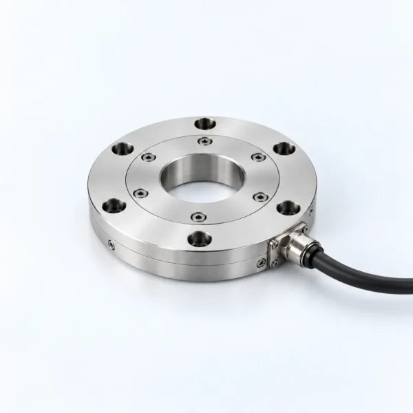
Six-Axis Force Torque Sensor for Robot Measurement
A force torque sensor measures the forces and moments acting at a robot interface so the control or test system can respond to contact. This page is an RFQ entry for robot wrists, end effectors, feet, assembly stations, force-controlled processes, and laboratory measurement. It is not a fixed sensor model or a claim of available stock. RobotPiece matches the measuring task, mechanical interface, signal requirements, and calibration expectations before a specific configuration is proposed.
A 6 axis force torque sensor is normally selected around all six channels: Fx, Fy, Fz, Mx, My, and Mz. A six axis force torque sensor cannot be chosen reliably from one axial capacity alone. Expected working loads, off-axis loads, transient events, allowable overload, resolution, accuracy, cross-talk, stiffness, sampling behavior, and installation preload can all affect the result. For a force torque sensor robot application, the control bandwidth and host interface matter alongside mechanical capacity. A multi axis force torque sensor used for testing may instead prioritize traceable calibration, repeatability, data logging, or flexible signal conditioning.
Selection and Engineering Requirements

For useful comparison, a 6 axis force torque sensor and a six axis force torque sensor refer to the same six-component measurement objective, but their ranges, mechanics, electronics, and calibration can differ. A force torque sensor robot installation should be checked at the actual mounting point. A multi axis force torque sensor used in a test rig may need a different signal chain and data-acquisition scope.
The comparison should keep working loads, transient loads, overload limits, signal electronics, and calibration deliverables separate.
Describe where the sensor sits in the load path and provide the expected force and moment ranges for normal operation, process peaks, collisions, and handling. If possible, include the tool geometry and the distance from the sensing origin to the applied load. That offset can create moments even when the external force appears modest. State the required measurement resolution, permissible error, repeatability objective, control-loop rate, and whether the readings are used for safety, closed-loop control, quality monitoring, or research.
Mechanical details should include the available outside diameter and height, through-hole need, mounting pattern, bolt size, locating features, cable direction, allowable mass, and adjacent materials. Electrical details should identify the preferred output or communication method, sample rate, supply, cable length, connector constraints, data acquisition equipment, and operating system or controller environment. Explain any temperature variation, moisture, dust, sterilization, vacuum, or electromagnetic conditions relevant to the installation.
Engineering Reference
This sensor engineering FAQ provides useful background on measurement range, saturation, overload, and cable conditions. It is used only to frame the inquiry and does not describe the specifications of a quoted sensor. Review the technical background.
Scope and Configuration to Confirm
The quoted scope may include only the sensing body, or it may include a cable, amplifier, interface module, acquisition unit, software, mounting adapter, and calibration documentation. None of these are assumed. The quotation should identify the coordinate convention, connector and pin definition, output format, calibration deliverables, overload conditions, and any installation guidance. If the sensor is incorporated between a robot flange and an end effector, both interfaces must be checked rather than inferred from an illustration.
Current specifications are confirmed per requirement. RobotPiece does not derive performance from housing size or present a generic image as the delivered model. Product-type illustrations are visual references only. Final dimensions, finish, cable arrangement, metrology documentation, and supplied accessories depend on the approved sensor configuration.
Inquiry Checklist
- Application, sensor location, tool geometry, and load application point
- Required Fx, Fy, Fz, Mx, My, and Mz working ranges and transient loads
- Resolution, accuracy, repeatability, cross-talk, stiffness, and bandwidth priorities
- Envelope, mounting drawings, through-hole, cable exit, connector, and cable length
- Output, sample rate, host controller, acquisition hardware, and software environment
- Calibration needs, quantity, destination, development schedule, and documentation needs
Send the load case and interface drawings through the RobotPiece contact page. Related sensing options are organized in the Sensors category.
Frequently Asked Questions
How do I choose the required force torque sensor ranges?
Use the highest credible loads at the sensor, including gravity, acceleration, process force, tool offset, impact, and abnormal events. Provide normal and transient cases separately so measurement sensitivity is not sacrificed by selecting an unnecessarily broad range.
Is a cable, amplifier, acquisition unit, and calibration certificate included?
Only if the quotation says so. The sensing body and signal chain are treated as separate scope items until the connector, output, cable, electronics, software, and calibration deliverables have been confirmed.
Image note: the cover is a conceptual product-type illustration, not a photograph of a confirmed model. Actual appearance, dimensions, connectors and supplied items must be confirmed in the quotation.
